1. Film/foil structure
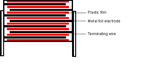
The film/foil structure is mainly used for capacitors with small capacitance (100pF~0.1µF). The advantage of this structure is that the metal foil electrode is easy to reach and the pulse strength is good.
The dielectric film breakdown of such capacitors will lead to short circuit and thus failure.
In order to avoid breakdown due to weak points in the dielectric, the chosen insulating film is always thicker than theoretically required by a value based on the specific breakdown strength of the material. Films smaller than 4µm are not used for such capacitors because of their high percentage of weak spots.
The thicker the insulating film, the adverse effect on the size and material use. In order to obtain a specific capacity, thicker insulating film must be used, the length of the film must also be increased. Therefore, the thicker the insulating film, the larger the volume of the winding elements.
A weak spot occurs when the upper and lower surfaces of the film are dented. The dielectric must be thick enough to achieve the desired breakdown strength.
Advantages: High pulse load capacity due to good contact between welding wire and foil electrode.
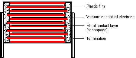
Larger capacitance capacitors (0.01µF~100µF larger) can also be manufactured for metalized capacitors. For metalized capacitors, vacuum aluminum plating (~0.03µm) on the insulating film is used as a conductive electrode. In case of breakdown, short circuit current will cause the metal coating to evaporate around the fault point. Without degrading the dielectric quality, an insulating region is formed, and the capacitor remains intact (self-healing). The resulting capacitance loss of a few pF is not important. Metallized capacitors can make full use of the breakdown strength of the insulating film. In the production of capacitors, the weak link is cured. This makes it possible to use the thinnest insulating film with a thickness of less than 1µm. Compared with the advantages of small size and self-healing properties of metallized capacitors, limited current loading capacity is a disadvantage due to the thin vacuum coated metal layer.
Advantages: Metallized structures have the most favorable capacity/volume values.
3. Metallized structure for pulse application
额定(直流)电压:250Vdc、400Vdc
Rated (AC) voltage :630Vdc, 1000Vdc, 1600Vdc, 2000Vdc
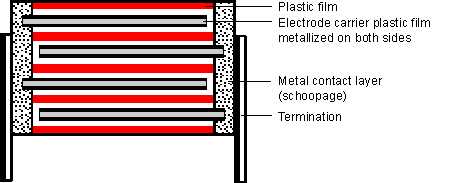
In order to overcome the single side the shortcoming of metalized capacitor current load ability is limited, wei di is developed with the high pulse application of special metal version, not direct evaporation on the dielectric film electrode (metal), and both sides of the plastic film by vacuum evaporation on aluminum, the double metal film and insulation film (film) rolled up, like film/foil capacitors.
By spraying metal and forming contacts, the two metal layers on the carrier film are connected together as conductors. Therefore, the carrier film is in the magnetic field free space, its dielectric properties are not important (the film in the magnetic field free space), and the fault self-healing process occurs on the double mask. Since both sides are metallized, this type of capacitor has the same good self-healing properties as single-sided metallized capacitors, which also has the advantage of better electrical conductivity and contact.
These capacitors can withstand very high pulse currents and are only slightly larger than single-sided metallized capacitors.
They provide high operational security in critical applications.
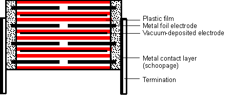
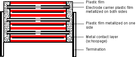
This capacitor type is suitable for highest current loads due to its thin film/foil construction with metallized electrode carrier. The capacitor is a series structure and the current carrying electrode is composed of two metal foils and a metallized carrier film as a floating electrode.
After insulation and bonding, the wires are connected to all edges of the winding elements. The floating electrode transmits current only through capacitive coupling. In this way, the advantages of self-healing (via metallized floating electrodes) are combined with the advantages of abnormally safe binding of the foil. As a result of the series, the value of the corona starting voltage is doubled.
Capacitors constructed in this manner are suitable for very high current ratings with maximum operational safety.
Advantage:
The highest pulse loading capacity is achieved due to good bonding (foil electrode and metallized electrode carrier film).
The floating electrode of metallized carrier film has good self-healing property.
Due to the series, the corona starting voltage value is doubled.

Figure 1: Schematic diagram of the self-healing process Figure 2: Insulation area after the self-healing process The self-healing process is initiated by electrical breakdown and takes about 10-8 seconds. In the breakdown channel, the dielectric is transformed into a highly compressed plasma, which is pushed out of the channel and laminates the dielectric open (FIG. 1).
In the diffusing plasma, the discharge continues at the metal electrode. The temperature is about 6000K, and an insulating area is formed around the original fault point (see Figure 2). This self-healing process takes a few microseconds, and the discharge in the plasma has stopped before a larger voltage loss can occur. This rapid extinction of the plasma is necessary to avoid further damage to the dielectric layer near the fault point.
The pressure between the layers must not be so great that the plasma can diffuse rapidly out of the breakdown channel. Most of the plasma enters the low field intensity region.
The perfect process of the self-healing process depends on the thickness of the metal coating, the chemical composition and the rate of applied voltage; Here, in addition to chemical composition, production conditions must also provide prerequisites for optimal self-healing.
Self-healing behavior as a quality criterion.